Reed Relay vs Solid State Relay: Which is Better for High Voltage Applications?
Introduction
Choosing the right switching technology for high-voltage applications is one of the most consequential decisions an engineer can make. Whether you’re designing an automated test equipment (ATE) system, a medical device, or a power distribution panel, the relay you select directly affects measurement accuracy, system reliability, safety compliance, and total cost of ownership.
The stakes are particularly high when voltages exceed a few hundred volts. A relay that fails to provide adequate isolation can result in arc-over, equipment damage, or — in safety-critical applications like medical devices — injury to operators or patients. Conversely, a relay with excessive contact resistance or leakage current can silently degrade the accuracy of precision measurements, leading to test failures, false pass/fail results, or unreliable data.
The two dominant technologies in the high-voltage switching space — reed relays and solid state relays (SSRs) — each bring distinct advantages and trade-offs. Yet engineers often default to one technology out of habit or familiarity rather than rigorous analysis. This article provides a structured, six-dimension comparison to help you make an informed choice for your specific high-voltage application.
How They Work
Reed Relays
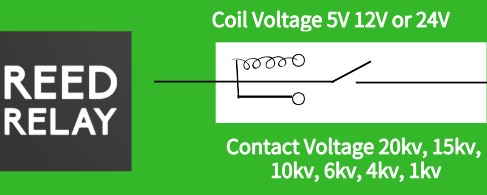
A reed relay consists of reed contacts — two ferromagnetic metal reeds sealed inside a glass capsule filled with inert gas — surrounded by an electromagnetic coil. When the coil is energized, the magnetic field pulls the reeds together, closing the circuit. When de-energized, the reeds spring apart, restoring an open circuit with a true physical air gap.
This mechanical switching action is the foundation of the reed relay’s exceptional isolation characteristics. There is no semiconductor junction in the signal path — just two metal contacts touching and separating in a sealed, contamination-free environment. High-voltage reed relays extend this principle with specialized contact materials, extended gap spacing between reeds, and robust encapsulation to achieve isolation voltages up to 20 kV or more.
The sealed glass envelope serves multiple purposes: it prevents oxidation and contamination of the contacts, eliminates arcing in atmospheric conditions, and contributes to stable contact resistance over billions of operations. The result is a switching element that combines high isolation with low, predictable contact resistance — a combination that is difficult to achieve with any other technology.
Solid State Relays
Solid state relays use semiconductor devices — typically MOSFETs, thyristors, or optocouplers — to switch electrical signals without any moving parts. An input control signal activates an LED or photodiode, which in turn triggers the output switching element through optical or electromagnetic coupling. This design eliminates mechanical wear entirely, but introduces other characteristics that must be considered in high-voltage applications.
The semiconductor junctions in SSRs inherently produce on-state resistance, leakage current in the off state, and a small offset voltage across the output stage. While these characteristics are acceptable or even irrelevant in many power switching applications, they become significant limitations in precision measurement and high-isolation designs. The isolation barrier — typically an optocoupler or capacitive coupling element — is rated for specific voltage levels (usually 1–5 kV) and can degrade over time due to semiconductor aging effects.
SSRs also require more complex drive circuitry compared to reed relays, including gate drivers, snubber networks for dv/dt protection, and often heat sinking for the output stage. These additional components increase board area, design complexity, and cost — factors that must be weighed against the SSR’s speed and lifecycle advantages.
Six-Dimension Comparison
The following table compares reed relays and solid state relays across six critical parameters for high-voltage applications. Understanding where each technology excels — and where it falls short — is essential for making the right selection.
| Parameter | Reed Relay | Solid State Relay | Winner |
|---|---|---|---|
| Isolation Voltage | Up to 20 kV or higher; true galvanic isolation via physical air gap | Typically 1–5 kV; limited by semiconductor junction breakdown | Reed |
| Contact Resistance | ~100 mΩ; stable over rated lifetime | 1–10 Ω on-state resistance; varies with temperature and current | Reed |
| Switching Speed | Microseconds (μs) typical; ~0.5 ms including reed bounce | Nanoseconds (ns) to low microseconds | SSR |
| Lifecycle | 1 billion+ operations at rated load; glass seal prevents wear | Theoretically unlimited mechanical life; no moving parts | SSR |
| Signal Integrity | Zero leakage current; no offset voltage; clean break-before-make | Leakage current in nA–μA range; offset voltage across output stage | Reed |
| Cost | Lower per-unit at low-to-mid volumes; simple drive circuit | Higher per-unit but scales at volume; more complex drive required | Reed (low vol) / SSR (high vol) |
Analysis by Dimension
Isolation Voltage is often the deciding factor in high-voltage designs. Reed relays achieve isolation through a physical air gap between open contacts, which is inherently robust and does not degrade with age. The isolation is a function of reed geometry and encapsulation — characteristics that are stable for the entire life of the component. Solid state relays rely on semiconductor isolation barriers — optocouplers or capacitive coupling — that are rated for specific voltage levels but can degrade with age and are vulnerable to transient overvoltage conditions. For applications above 5 kV, reed relays are frequently the only practical switching option available in a compact, reliable package.
Contact Resistance directly affects measurement accuracy in test and instrumentation applications. Reed relays offer contact resistance around 100 mΩ that remains stable across billions of cycles. SSRs exhibit on-state resistance of 1–10 Ω that increases with temperature — a phenomenon known as thermal drift — introducing systematic errors in precision measurements. In a voltage divider or current measurement circuit, even 1 Ω of additional resistance can produce significant measurement error at low signal levels.
Switching Speed favors SSRs for applications requiring rapid, high-frequency switching. While reed relays can switch in microseconds with proper drive circuits and controlled bounce times, SSRs can toggle in nanoseconds without any contact bounce. However, for most high-voltage test and measurement applications, reed relay speed is more than adequate — the DUT response time or measurement integration period typically dominates the overall test time anyway.
Lifecycle is where SSRs traditionally hold an advantage, but the gap has narrowed considerably. Modern reed relays rated for 1 billion+ operations provide decades of service even in high-cycling applications. For context, a system cycling 100 times per second would take over 116 days of continuous operation to reach 1 billion cycles. In practice, most reed relay applications cycle at far lower rates, making lifecycle a non-issue for the vast majority of designs.
Signal Integrity is critical in precision measurement and instrumentation. Reed relays provide an open circuit with essentially zero leakage current and no offset voltage when open — essential characteristics for high-impedance measurements, picoammeter circuits, and low-level signal switching. SSRs always present some leakage path (typically nanoamps to microamps) and an offset voltage across the output stage, which can corrupt sensitive measurements, particularly in semiconductor parametric test and low-current data acquisition applications.
Cost dynamics depend heavily on production volume. Reed relays require minimal drive circuitry — a simple transistor driver and a flyback diode suffice — keeping total system cost low at prototype and low-volume production. SSRs demand more complex gate drive circuits, protection networks, and often heat sinking, adding both component cost and board area. However, at very high production volumes where automated assembly and semiconductor economics apply, SSR per-unit costs can become competitive. The engineering overhead of SSR integration is also higher, which favors reed relays for designs that prioritize time-to-market.
Application Matrix
The table below maps eight common high-voltage applications to the preferred relay technology based on the dominant requirements of each use case. This matrix should serve as a starting point — your specific design constraints may shift the recommendation in either direction.
| Application | Preferred Technology | Key Reason |
|---|---|---|
| Automated Test Equipment (ATE) / Semiconductor Test | Reed | Low contact resistance, zero leakage, high isolation for accurate parametric measurements |
| Medical Devices (Defibrillator, MRI) | Reed | High isolation voltage, safety-critical reliability, no semiconductor failure modes |
| EV Battery Testing | Reed | High voltage isolation for series-connected cells, measurement accuracy for SOC estimation |
| Solar Inverter Switching | SSR | High-speed PWM switching, high cycle count, power handling |
| Industrial Motor Control | SSR | Fast switching, no contact bounce, continuous high-current operation |
| Telecom Line Switching | Reed | Low signal distortion, high isolation between lines, long operational life |
| Data Acquisition Systems | Reed | Signal integrity, low leakage, minimal offset voltage for accurate analog readings |
| Power Distribution | SSR | High-speed protection switching, scalability, integration with digital control systems |
When to Choose Reed Relays
Reed relays are the preferred choice when your application demands one or more of the following:
- High isolation voltages above 5 kV — The physical air gap in a reed relay provides unmatched galvanic isolation that semiconductor barriers cannot replicate at extreme voltages. For applications requiring 10 kV, 15 kV, or 20 kV isolation, high-voltage reed relays are often the only viable option.
- Precision measurement accuracy — Zero leakage current and negligible contact resistance ensure that the relay doesn’t introduce measurement errors. This makes reed relays essential for ATE, semiconductor test, and data acquisition systems where accuracy directly impacts product quality.
- Signal integrity in low-level switching — When switching microvolt or microamp signals, the absence of offset voltage and leakage paths preserves signal fidelity. Any semiconductor-based switch in the signal path introduces artifacts that degrade measurement quality.
- Safety-critical applications — Medical devices such as defibrillators and MRI systems require fail-safe isolation that only a true galvanic break can provide. Reed relays meet stringent medical safety standards with inherent physical isolation that doesn’t depend on semiconductor integrity.
- Low-to-medium volume production with simple drive circuits — Reed relays minimize total system cost and design complexity when production volumes don’t justify the integration overhead of SSR drive and protection circuitry. Time-to-market is also faster with reed relay designs.
When to Choose Solid State Relays
Solid state relays are the better fit when your application prioritizes:
- Ultra-high switching speed — Nanosecond-class switching is essential for applications like solar inverter PWM control, high-frequency power conversion, and fast protection circuits where microsecond response times are unacceptable.
- Extreme cycling at moderate voltages — When the application demands continuous high-frequency switching below 5 kV and signal accuracy is secondary, SSRs offer theoretically infinite mechanical life without contact degradation.
- Zero contact bounce — SSRs produce no mechanical bounce, making them suitable for applications where bounce-induced transients are unacceptable or where downstream circuits are sensitive to switching noise.
- High-volume production — At scale, SSRs can achieve lower per-unit costs despite more complex drive and protection circuitry. The NRE overhead is amortized across large production runs.
- Harsh mechanical environments — The absence of moving parts makes SSRs inherently resistant to vibration and shock, though properly packaged reed relays in ruggedized housings also perform well in demanding environments.
Hybrid Approaches
In practice, many high-voltage systems benefit from combining both technologies rather than committing exclusively to one. A hybrid design leverages the strengths of each technology where they matter most, optimizing both performance and cost.
For example, a comprehensive ATE system might use high-voltage reed relays for the signal path where measurement accuracy and isolation are paramount, while employing SSRs for auxiliary functions like relay matrix scanning, power supply sequencing, or LED indicators where speed takes priority over precision.
Similarly, an EV battery management test system could use reed relays for cell voltage measurement multiplexing — where leakage current directly affects state-of-charge estimation accuracy — while using SSRs for fast current interrupt testing and charge/discharge path switching.
In telecommunications infrastructure, reed relays handle the sensitive signal path switching with minimal distortion, while SSRs manage power distribution and protection circuits where high-speed response to fault conditions is critical.
The key principle for hybrid designs is to evaluate each switching point in your system independently. Ask: what does this specific switch need to do? If the answer prioritizes isolation, accuracy, or signal integrity, lean toward reed relays. If speed, infinite cycling, or bounce-free operation dominate, consider SSRs. Most well-designed high-voltage systems will benefit from using both technologies strategically.
Related Resources
For more detailed guidance on selecting and implementing reed relays in your high-voltage designs, explore these resources:
- How to Choose the Right High Voltage Reed Relay for Your Application — A step-by-step selection guide covering voltage ratings, contact configurations, and packaging options.
- Common Reed Relay Failures and How to Prevent Them — Practical guidance on avoiding the most common failure modes in reed relay designs.
- High Voltage DC Contact Relays — Browse our complete range of high-voltage reed relay products.
- Contact Us — Speak with our engineering team about your specific high-voltage switching requirements.