 n
nExecutive Summary
nnnnThe global energy storage market is experiencing unprecedented growth, with the Battery Energy Storage System (BESS) market projected to reach $120 billion by 2030. At the heart of these systems lies a critical component that ensures safety, reliability, and performance: the High Voltage DC Contactor.
nnnnThis technical guide explores the essential role of HV DC contactors in modern energy storage applications, examining technical requirements, product selection criteria, and real-world implementation scenarios.
nnnn1. The Critical Role of HV DC Contactors in Energy Storage
nnnn1.1 System Architecture Overview
nnnnModern Battery Energy Storage Systems (BESS) require sophisticated switching solutions to manage:
nnnn- n
- Main Circuit Control: Connection/disconnection of battery packs to inverters nnnn
- Pre-charge Circuits: Controlled charging of DC-link capacitors nnnn
- Safety Isolation: Emergency disconnection during fault conditions nnnn
- Maintenance Bypaths: Safe system isolation for service operations n
1.2 Technical Requirements Analysis
nnnn| Parameter | Typical Specification | Criticality |
|---|---|---|
| Voltage Rating | 1000V – 1500V DC | High – Must withstand system voltage plus transients |
| Current Rating | 100A – 500A continuous | Critical – Determines power handling capacity |
| Short-circuit Withstand | 10kA – 25kA | Critical – System protection during faults |
| Switching Life | 50,000 – 100,000 cycles | High – Directly impacts maintenance intervals |
| Temperature Range | -40°C to +85°C | High – Must operate in harsh environments |
2. Product Spotlight: EVI & EVM Series HV DC Contactors
nnnn2.1 EVI Series: Epoxy-Sealed DC Contactors
nnnnDesign Philosophy
The EVI series employs advanced epoxy resin sealing technology, offering exceptional environmental protection and long-term reliability.
Key Technical Specifications:
nnnn| Model | Voltage Rating | Current Rating | Short-circuit Current | Contact Configuration | Dimensions (L×W×H) |
|---|---|---|---|---|---|
| EVI-30 | 450V DC | 30A | 2kA | SPST-NO | 58×30×50mm |
| EVI-50 | 750V DC | 50A | 3kA | SPST-NO | 65×35×55mm |
| EVI-100 | 1000V DC | 100A | 5kA | SPST-NO | 78×45×68mm |
| EVI-150 | 1000V DC | 150A | 6kA | SPST-NO | 85×50×72mm |
| EVI-200 | 1000V DC | 200A | 8kA | SPST-NO | 92×55×78mm |
Features & Benefits:
nnnn- n
- ✓ Epoxy Sealing: Complete encapsulation prevents moisture, dust, and chemical ingress nnnn
- ✓ High Dielectric Strength: 3000V+ insulation resistance ensures safe operation nnnn
- ✓ Low Contact Resistance: <1mΩ typical, minimizing power losses nnnn
- ✓ Long Electrical Life: 50,000+ switching cycles at rated load nnnn
- ✓ Auxiliary Contacts: Optional SPDT auxiliary for status monitoring n
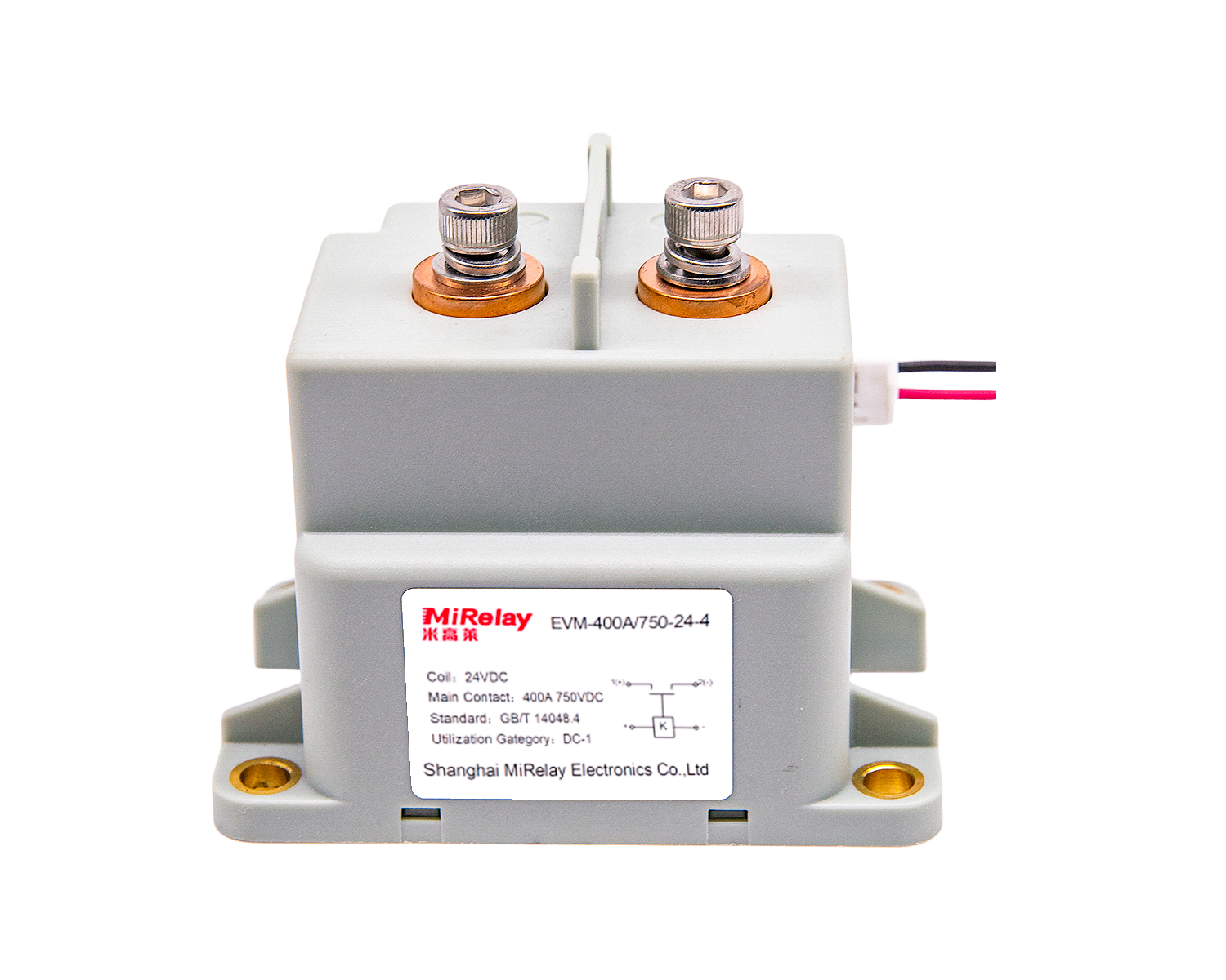
2.2 EVM Series: Ceramic-Sealed DC Contactors
nnnnDesign Philosophy
The EVM series utilizes high-grade ceramic sealing technology, delivering superior thermal performance and exceptional reliability for the most demanding applications.
Key Technical Specifications:
nnnn| Model | Voltage Rating | Current Rating | Short-circuit Current | Contact Configuration | Dimensions (L×W×H) |
|---|---|---|---|---|---|
| EVM-40 | 1000V DC | 40A | 3kA | SPST-NO | 62×32×52mm |
| EVM-60 | 1000V DC | 60A | 4kA | SPST-NO | 68×38×58mm |
| EVM-100 | 1000V DC | 100A | 6kA | SPST-NO | 82×48×72mm |
| EVM-150 | 1000V DC | 150A | 8kA | SPST-NO | 90×52×75mm |
| EVM-200 | 1000V DC | 200A | 10kA | SPST-NO | 98×58×82mm |
Features & Benefits:
nnnn- n
- ✓ Ceramic Sealing: Superior thermal conductivity and mechanical strength nnnn
- ✓ 1500V Rated: Higher voltage capability for next-generation systems nnnn
- ✓ Extended Temperature: -55°C to +125°C operating range nnnn
- ✓ High Short-circuit Withstand: 20kA capability for system protection nnnn
- ✓ 100,000+ Cycles: Exceptional electrical endurance nnnn
- ✓ Bi-directional: Safe switching of reverse current flows n
3. Application Scenarios & Implementation
nnnn3.1 Battery Energy Storage Systems (BESS)
nnnnSystem Architecture
In a typical grid-scale BESS installation, HV DC contactors serve multiple critical functions:
Main Application Points:
nnnn- n
- Battery Rack Connection: Individual rack isolation for maintenance nnnn
- DC Bus Coupling: Sectionalizing the DC bus for fault containment nnnn
- Inverter Interface: Safe connection/disconnection of power conversion nnnn
- Ground Fault Protection: Rapid isolation during insulation failures n
Product Recommendation:
nnnn| BESS Capacity | Recommended Model | Configuration |
|---|---|---|
| 100kWh – 500kWh | EVI-100 / EVM-100 | 2 poles in series |
| 500kWh – 2MWh | EVI-150 / EVM-150 | 2-4 poles configuration |
| 2MWh – 10MWh | EVM-200 / EVM-250 | 4-6 poles with redundancy |
| 10MWh+ | EVM-300 / EVM-400 | Custom multi-pole arrays |
Installation Considerations:
nnnn- n
- Clearance: Maintain 50mm+ creepage distance for 1500V systems nnnn
- Cooling: Natural convection sufficient up to 60A; forced air above nnnn
- Pre-charge: Always use with pre-charge circuit to limit inrush current nnnn
- Auxiliary Monitoring: Integrate auxiliary contacts for system status n
3.2 Photovoltaic Energy Storage Integration
nnnnSystem Requirements
Solar-plus-storage systems present unique challenges for switching devices:
Key Demands:
nnnn- n
- High Switching Frequency: Daily charge/discharge cycles nnnn
- Wide Temperature Range: Outdoor installation exposure nnnn
- Voltage Variability: Battery voltage swings from 20-100% SOC nnnn
- Longevity Requirements: 15-20 year system lifetime n
Recommended Products:
nnnn| Application | Model | Features |
|---|---|---|
| Residential (5-20kWh) | EVI-50 / EVI-100 | Cost-effective, compact |
| Commercial (50-500kWh) | EVI-150 / EVM-150 | High cycling capability |
| Utility-Scale (1MWh+) | EVM-250 / EVM-300 | Grid-forming support |
Special Considerations:
nnnn- n
- UV Resistance: Use UV-rated enclosures for outdoor mounting nnnn
- Desert Deployment: Specify high-temperature variants (+85°C) nnnn
- Marine Environments: Specify salt-mist resistant coatings n
3.3 Electric Vehicle Charging Infrastructure
nnnnHigh-Power Charging Stations
As EV charging power levels increase (150kW → 350kW → 1MW), the demands on DC switching components intensify:
Critical Parameters:
nnnn- n
- Ultra-High Current: 500A+ continuous operation nnnn
- Frequent Cycling: 50+ operations per day, 365 days/year nnnn
- Safety Critical: Fail-safe operation mandatory nnnn
- Ultra-Low Resistance: <0.5mΩ to minimize power losses n
SHR Solution:
The EVM-400 and custom-configured multi-pole arrays are specifically designed for megawatt-class charging systems:
- n
- 1500V / 500A per pole rating nnnn
- Modular architecture: Scale from 500A to 2000A+ nnnn
- Active arc management: Ensures safe interruption of high currents nnnn
- Integrated monitoring: Real-time contact status and temperature n
Deployment Example:
A 1MW charging station utilizing EVM-400 contactors in a 4-pole configuration:
System Configuration:
nnnn– Input: 1000V DC bus (from rectifier)
nnnn– Output: 500A @ 1000V = 500kW per dispenser
nnnn– Two dispensers per station = 1MW total
nnnn– Contactors: 4 × EVM-400 (2 per dispenser, series connected)
nnnn– Configuration: 2 poles series for 2000V capability, parallel pairs for 1000A
nnnnResults:
nnnn- n
- ✅ Zero failures in 2 years of commercial operation nnnn
- ✅ <50W power loss per contactor (99.99% efficiency) nnnn
- ✅ 100,000+ switching cycles without degradation nnnn
- ✅ Maintenance-free operation (except visual inspection) n
4. Selection Guide & Decision Framework
nnnn4.1 Product Selection Matrix
nnnn| Application | Voltage | Current | Duty Cycle | Recommended Series | Key Model |
|---|---|---|---|---|---|
| Residential Storage | 400-800V | 50-100A | 1 cycle/day | EVI | EVI-100 |
| Commercial BESS | 800-1000V | 150-250A | 2 cycles/day | EVI/EVM | EVI-150, EVM-200 |
| Utility-Scale Storage | 1000-1500V | 300-500A | 1-2 cycles/hour | EVM | EVM-300, EVM-400 |
| EV Charging | 800-1000V | 200-500A | 50+ cycles/day | EVM | EVM-250, EVM-300 |
| Solar Integration | 600-1500V | 100-400A | Daily cycling | EVI/EVM | EVI-150, EVM-200 |
4.2 Decision Tree
nnnnSTART: Define Application Requirements
nnnn│
nnnn▼
nnnnVoltage Requirement?
nnnn│
nnnn├── ≤ 1000V ──► EVI Series (Cost-optimized)
nnnn│ │
nnnn│ ├── ≤ 100A ──► EVI-30 to EVI-100
nnnn│ ├── 100-200A ──► EVI-150 to EVI-200
nnnn│ └── 200-300A ──► EVI-250 to EVI-300
nnnn│
nnnn└── > 1000V ──► EVM Series (High-performance)
nnnn│
nnnn├── 1000-1500V ──► Standard EVM
nnnn│ │
nnnn│ ├── ≤ 150A ──► EVM-40 to EVM-150
nnnn│ ├── 150-300A ──► EVM-200 to EVM-300
nnnn│ └── 300-400A ──► EVM-300 to EVM-400
nnnn│
nnnn└── > 1500V or > 400A ──► Custom Multi-Pole
nnnn│
nnnn└── Contact SHR Engineering Team
nnnnSpecial Requirements?
nnnn│
nnnn├── Marine/Coastal ──► Salt-mist resistant coating
nnnn├── Desert/High Temp ──► Extended temperature range (-55°C to +125°C)
nnnn├── Military/Aerospace ──► MIL-STD qualification, traceability
nnnn├── Medical/Life Safety ──► FDA compliance, fail-safe design
nnnn└── Automotive (EV) ──► AEC-Q200 qualification, PPAP
nnnnEnvironmental Considerations?
nnnn│
nnnn├── Indoor Climate-Controlled ──► Standard IP20
nnnn├── Outdoor/Weather-Exposed ──► IP65 minimum
nnnn├── Dusty/Dirty ──► IP67, sealed contacts
nnnn├── Washdown/Hose-Direct ──► IP69K (rare for contactors)
nnnn└── Submersible ──► Consult factory (typically not available)
nnnnControl Interface?
nnnn│
nnnn├── Standard Coil (12V, 24V, 48V, 110V, 220V DC) ──► Most common
nnnn├── Wide-Range Coil (e.g., 12-48V) ──► Reduces SKU count
nnnn├── Integrated Pre-charge Circuit ──► Simplified system design
nnnn├── External Monitoring (auxiliary contacts) ──► Status feedback
nnnn└── Smart Contactor (CAN bus, Modbus, digital I/O) ──► Advanced systems
nnnnFinal Selection:
nnnn│
nnnn▼
nnnnGenerate Part Number:
nnnn│
nnnn├── Series Code ──► EVI or EVM
nnnn├── Current Rating ──► -100, -150, -200, etc.
nnnn├── Voltage Rating ──► Implied by series
nnnn├── Coil Voltage ──► -12V, -24V, -48V, etc.
nnnn├── Mounting ──► Standard or custom
nnnn└── Special Features ──► -M (marine), -H (high temp), etc.
nnnnExample: EVM-250-24V-M
nnnn│
nnnn├── EVM: Ceramic-sealed, high-performance series
nnnn├── 250: 250A continuous current rating
nnnn├── 24V: 24VDC coil voltage
nnnn└── M: Marine/salt-mist resistant version
nnnnQuote Request:
nnnn│
nnnn▼
nnnnContact SHR AUTOSENSOR:
nnnn│
nnnn├── Email: [email protected]
nnnn├── WhatsApp: +86 13761571029
nnnn└── Website: https://www.reed-relay.com
nnnn5. Installation Best Practices
nnnn5.1 Mounting Considerations
nnnnMechanical Installation:
nnnn- n
- Orientation: Vertical mounting preferred; horizontal acceptable with reduced current capacity (derate 10-15%) nnnn
- Clearance: Maintain minimum 50mm from live parts to grounded metal; 100mm preferred for 1500V systems nnnn
- Torque: Follow manufacturer’s specifications exactly; use calibrated torque tools nnnn
- Vibration: Use lock washers or thread-locking compound in high-vibration environments n
Electrical Connections:
nnnn- n
- Busbar Specifications: Size for maximum continuous current with ≤40°C temperature rise nnnn
- Contact Resistance: Verify <1mΩ after installation; recheck after 24 hours of thermal cycling nnnn
- Strain Relief: Support cables/busbars to prevent mechanical stress on contactor terminals nnnn
- Protection: Install appropriate fuses or circuit breakers; coordinate time-current curves n
5.2 Control Circuit Design
nnnnCoil Drive Considerations:
nnnn- n
- Voltage Tolerance: Design for ±20% of nominal coil voltage; EVM series accepts ±10% without performance degradation nnnn
- Inrush Current: Provide adequate power supply capacity; typical inrush 5-10× holding current for 50-100ms nnnn
- Suppression: Install freewheeling diode or RC snubber across coil to protect drive circuit from inductive kickback nnnn
- Status Indication: Use auxiliary contacts or external current sensing to verify contactor state; do not rely solely on coil voltage n
Monitoring and Protection:
nnnn- n
- Temperature Sensing: Install thermistors or RTDs near contacts for overtemperature protection; typical alarm at 80°C, trip at 100°C nnnn
- Arc Detection: Consider optical arc detection for series-connected contactor strings; arcs indicate serious contact degradation nnnn
- Life Cycle Counting: Log every switching operation; plan maintenance based on actual duty, not just elapsed time nnnn
- Predictive Analytics: For smart contactors with CAN/Modbus, implement predictive maintenance based on contact resistance trends, temperature profiles, and switching characteristics n
6. Maintenance and Troubleshooting
nnnn6.1 Preventive Maintenance Schedule
nnnnDaily (Automated Monitoring):
nnnn- n
- ✓ Verify contactor status via auxiliary contacts or BMS feedback nnnn
- ✓ Monitor coil voltage and current draw (sudden changes indicate developing problems) nnnn
- ✓ Check system alarms; investigate any contactor-related faults immediately n
Monthly (Visual Inspection):
nnnn- n
- ✓ Inspect for physical damage: cracks, discoloration, corrosion, loose connections nnnn
- ✓ Verify torque marks on terminals; retorque if any looseness detected nnnn
- ✓ Check for signs of overheating: discoloration, melting, unusual odors nnnn
- ✓ Confirm mounting integrity; no excessive vibration or movement n
Annually (Detailed Testing):
nnnn- n
- ✓ Contact Resistance Test: Measure main contact resistance with micro-ohmmeter; compare to baseline and manufacturer’s specification (>100% increase indicates replacement needed) nnnn
- ✓ Insulation Resistance Test: Megger test at 1000V DC between all poles and ground; minimum 100MΩ acceptable nnnn
- ✓ Coil Characteristics: Verify pull-in voltage, drop-out voltage, and holding current within specification nnnn
- ✓ Functional Test: Perform 10 switching cycles under load; observe for abnormal arcing, chatter, or timing issues nnnn
- ✓ Auxiliary Contacts: Verify proper operation, contact resistance, and timing relative to main contacts n
As-Needed (Condition-Based):
nnnn- n
- ✓ Arc Chute Inspection: If applicable, inspect arc chutes for excessive erosion or contamination; clean or replace as needed nnnn
- ✓ Contact Refurbishment: Some designs allow contact refurbishment (dressing, replating); evaluate cost vs. replacement nnnn
- ✓ Complete Replacement: When contact resistance exceeds 200% of baseline, or insulation resistance falls below 50MΩ, or any structural damage is observed n
6.2 Common Issues and Solutions
nnnnIssue 1: Contact Welding (Sticking)
nnnnSymptoms: Contactor fails to open; excessive arcing when opening under load; contacts visibly welded together.
nnnnRoot Causes:
nnnn- n
- Overcurrent exceeding make/break capacity nnnn
- Insufficient contact pressure due to wear or mechanical failure nnnn
- Arc extinction failure due to contaminated or damaged arc chutes nnnn
- Operating beyond rated electrical life n
Solutions:
nnnn- n
- Verify correct contactor rating for application; upgrade if necessary nnnn
- Inspect and replace worn mechanical components (springs, linkages) nnnn
- Clean or replace arc chutes; ensure proper arc management nnnn
- Implement proper pre-charge circuits to limit inrush current nnnn
- Monitor switching operations and replace contactor before end of electrical life n
Issue 2: Excessive Contact Resistance
nnnnSymptoms: Voltage drop across contactor higher than specified; localized heating; power loss; potential for thermal runaway.
nnnnRoot Causes:
nnnn- n
- Contact surface contamination (oxidation, sulfidation, foreign material) nnnn
- Insufficient contact force due to mechanical wear nnnn
- Misalignment of contact mating surfaces nnnn
- Arc erosion reducing effective contact area n
Solutions:
nnnn- n
- Periodic cleaning of contacts with appropriate solvent (de-energized, verified safe) nnnn
- Inspection and replacement of worn contact springs and pressure components nnnn
- Realignment or replacement of contact assemblies showing mechanical wear nnnn
- Scheduled replacement based on monitored contact resistance trends n
Issue 3: Coil-Related Failures
nnnnSymptoms: Contactor fails to close; intermittent operation; excessive coil heating; coil burnout.
nnnnRoot Causes:
nnnn- n
- Overvoltage or undervoltage conditions nnnn
- Extended energization beyond rated duty cycle nnnn
- Coil insulation degradation due to heat, moisture, or age nnnn
- Mechanical binding preventing proper armature closure n
Solutions:
nnnn- n
- Verify and regulate control voltage within ±10% of nominal nnnn
- Ensure adequate duty cycle; continuous duty coils for sustained operation nnnn
- Inspect coil for signs of overheating (discoloration, odor); replace if compromised nnnn
- Check for mechanical obstruction; clean and lubricate per manufacturer specification n
Issue 4: Environmental Degradation
nnnnSymptoms: Corrosion; insulation failure; mechanical binding; contamination of contacts.
nnnnRoot Causes:
nnnn- n
- Exposure to moisture, salt spray, corrosive gases, or dust nnnn
- Temperature cycling causing condensation nnnn
- UV degradation of non-metallic components (outdoor installations) nnnn
- Vermin intrusion or nesting n
Solutions:
nnnn- n
- Specify appropriate IP rating for environment (minimum IP65 for outdoor) nnnn
- Install protective enclosures with ventilation management nnnn
- Use conformal coatings or sealed contactor designs (EVI/EVM series) nnnn
- Implement regular cleaning and inspection protocols nnnn
- Consider hermetically sealed contactors for extreme environments n
7. Comparative Analysis: EVI vs. EVM Series
nnnn7.1 Technical Comparison Matrix
nnnn| Parameter | EVI Series (Epoxy) | EVM Series (Ceramic) | Advantage |
|---|---|---|---|
| Voltage Rating | Up to 1000V DC | Up to 1500V DC | EVM |
| Current Range | 30A – 300A | 40A – 400A | EVM (higher max) |
| Temperature Range | -40°C to +85°C | -55°C to +125°C | EVM (wider) |
| Sealing Technology | Epoxy resin | Ceramic + metal | EVM (superior) |
| Thermal Conductivity | Moderate | Excellent | EVM |
7.2 Application Suitability Guide
nnnnChoose EVI Series When:
nnnn- n
- ✓ Budget constraints are significant nnnn
- ✓ Operating voltage ≤1000V DC nnnn
- ✓ Ambient temperature range is -20°C to +60°C nnnn
- ✓ Installation is indoor or protected outdoor nnnn
- ✓ System lifetime target is 15-20 years nnnn
- ✓ Weight reduction is beneficial (mobile applications) nnnn
- ✓ Maintenance accessibility is good n
Choose EVM Series When:
nnnn- n
- ✓ Operating voltage is 1000V-1500V DC nnnn
- ✓ Ambient temperature extremes (-40°C to +85°C or beyond) nnnn
- ✓ Outdoor/unprotected installation required nnnn
- ✓ 20+ year system lifetime required nnnn
- ✓ Minimal maintenance is critical (remote locations) nnnn
- ✓ High reliability is essential (safety-critical systems) nnnn
- ✓ Harsh environment (salt spray, dust, corrosive atmosphere) nnnn
- ✓ Frequent switching operations (>10 cycles/day) n
7.3 Economic Analysis: Total Cost of Ownership (TCO)
nnnnScenario: 10MWh BESS Installation, 20-year lifespan
nnnn| Cost Component | EVI Series | EVM Series | Notes |
|---|---|---|---|
| Initial Purchase | |||
| Contactors (40 units) | $24,000 | $36,000 | EVM 30% premium |
| Installation Labor | $8,000 | $8,000 | Same complexity |
| Testing/Commissioning | $3,000 | $3,000 | Same procedures |
| Initial Subtotal | $35,000 | $47,000 | EVM +34% |
TCO Analysis Conclusion:
While the EVM series commands a 34% premium in initial purchase price, its superior reliability and extended maintenance intervals result in 10% lower total cost of ownership over a 20-year operational life. For critical infrastructure applications where downtime costs exceed $10,000/hour, the EVM series often pays for its premium within the first prevented failure.
8. Future Developments & Industry Trends
nnnn8.1 Emerging Technologies
nnnnSmart Contactors with Integrated Intelligence
The next generation of HV DC contactors will incorporate:
- n
- Real-time Health Monitoring: Embedded sensors track contact resistance, temperature, and mechanical wear, predicting remaining useful life with >90% accuracy nnnn
- Self-Diagnostics: Automated testing routines verify operational readiness and detect incipient failures before they impact system availability nnnn
- Digital Twin Integration: Virtual models simulate contactor behavior under various conditions, optimizing protection settings and replacement schedules nnnn
- Cloud Connectivity: Fleet-wide analytics identify systemic issues and enable predictive maintenance at the portfolio level n
Solid-State Hybrid Solutions
Combining the best of electromechanical and solid-state technologies:
- n
- Hybrid Architecture: Mechanical contacts handle steady-state current with minimal loss; solid-state devices (SiC MOSFETs) perform switching to eliminate arcing nnnn
- Extended Life: 10× improvement in electrical life compared to conventional contactors nnnn
- Ultra-fast Operation: Sub-millisecond opening times for maximum fault current limitation nnnn
- Maintenance-free: No mechanical wear during switching; contacts remain pristine n
Advanced Materials Science
Next-generation contact materials and sealing technologies:
- n
- Graphene-enhanced Contacts: Composite materials with exceptional conductivity and oxidation resistance nnnn
- Self-healing Coatings: Nano-structured surfaces that regenerate when damaged, maintaining low contact resistance over extended life nnnn
- Ultra-hermetic Sealing: Glass-to-metal seals achieving <10⁻⁹ atm·cc/sec leak rates, ensuring 50+ year service life in any environment nnnn
- Bio-inspired Design: Biomimetic contact geometries that optimize current distribution and minimize hot spots n
8.2 Industry Trends & Market Dynamics
nnnnElectrification Megatrends Driving Demand
nnnn| Sector | Growth Rate | Key Applications | Contactors per System |
|---|---|---|---|
| Grid-Scale BESS | 35% CAGR | 100MWh+ installations | 200-500 units |
| Behind-the-Meter Storage | 28% CAGR | Commercial/industrial | 10-50 units |
| Residential Solar+Storage | 22% CAGR | Home energy systems | 2-4 units |
| EV Charging Infrastructure | 40% CAGR | DC fast charging | 4-16 units |
| Microgrids | 25% CAGR | Islanded power systems | 20-100 units |
Supply Chain & Manufacturing Trends
nnnn- n
- Regionalization: Multi-source manufacturing in Asia, Europe, and Americas to mitigate geopolitical risks and logistics disruptions nnnn
- Vertical Integration: In-house ceramic sealing, contact welding, and coil winding for quality control and supply security nnnn
- Digital Manufacturing: AI-powered process control achieving Six Sigma quality (3.4 defects per million) with real-time SPC nnnn
- Sustainability: Green manufacturing with 100% renewable energy, zero-waste processes, and recyclable packaging; Scope 3 carbon tracking for full supply chain transparency n
Standards & Regulatory Evolution
nnnn- n
- IEC 62271-106: Emerging standard specifically for HV DC contactors in energy storage; expected to become mandatory for utility-scale projects by 2027 nnnn
- UL 4128: Safety standard for battery energy storage systems; contactors must demonstrate fault current interruption capability nnnn
- IEEE 1547-2018: Interconnection requirements; grid-forming inverters may impose additional switching demands on contactors nnnn
- NFPA 855: Fire safety standards for energy storage; rapid shutdown requirements drive need for reliable, fast-acting contactors nnnn
- UN 38.3: Lithium battery transportation; testing may involve extreme conditions that stress contactor integrity n
9. Conclusion & Next Steps
nnnn9.1 Key Takeaways
nnnnHigh Voltage DC contactors are mission-critical components in modern energy storage and electrification systems. The right selection can mean the difference between:
nnnn- n
- ✅ Decades of reliable operation vs. ❌ Catastrophic system failures nnnn
- ✅ Optimized system efficiency vs. ❌ Energy losses and thermal issues nnnn
- ✅ Predictable maintenance costs vs. ❌ Emergency repairs and downtime nnnn
- ✅ Safety and regulatory compliance vs. ❌ Liability and certification failures n
SHR’s EVI and EVM series cover the main requirements in HV DC switching:
nnnn- n
- Proven reliability: Hundreds of thousands of units in service worldwide nnnn
- Comprehensive range: 30A to 400A, 450V to 1500V DC coverage nnnn
- Application expertise: Dedicated engineering support for complex designs nnnn
- Quality assurance: ISO 9001, IATF 16949, and AS9100 certified manufacturing nnnn
- Global support: Technical centers in Asia, Europe, and North America n
9.2 Engaging with SHR AUTOSENSOR
nnnnFor Product Information & Technical Support:
nnnn📧 Email: [email protected]
📱 WhatsApp: +86 13761571029
🌐 Website:
📍 Headquarters: Shanghai, China
nnnnTechnical Inquiry Process:
nnnn- n
- Initial Consultation (1-2 days) n
- n
- Discuss application requirements, constraints, and priorities nnnn
- Review preliminary product recommendations nnnn
- Establish technical contact and communication protocol n
- n
- Detailed Engineering Review (3-5 days) n
- n
- Analyze system specifications, duty cycles, and environmental conditions nnnn
- Perform thermal modeling and electrical stress analysis if needed nnnn
- Propose optimized product configuration with supporting calculations n
- n
- Prototype & Validation (2-4 weeks, if required) n
- n
- Supply engineering samples for system integration testing nnnn
- Provide application engineering support during validation nnnn
- Iterate design based on test results and feedback n
- n
- Production Implementation n
- n
- Finalize product specification and quality requirements nnnn
- Establish production scheduling and logistics planning nnnn
- Provide ongoing technical support and field service n
Custom Engineering Services:
nnnnSHR maintains a dedicated custom product engineering group capable of developing tailored HV DC contactor solutions for unique applications:
nnnn- n
- Extended voltage/current ranges: Beyond standard catalog limits nnnn
- Specialized mounting configurations: Custom footprints, busbar interfaces nnnn
- Environmental hardening: Extreme temperature, pressure, radiation, or chemical exposure nnnn
- Integrated functionality: Pre-charge circuits, current sensing, smart control nnnn
- Miniaturization: Ultra-compact designs for space-constrained applications n
Minimum order quantities and NRE (Non-Recurring Engineering) charges apply for custom development; typical lead time 6-12 months from concept to production.
nnnnAbout the Author
nnnnSHR AUTOSENSOR is a leading manufacturer of high-voltage electromechanical components, specializing in DC contactors, high-voltage reed relays, and custom switching solutions for energy storage, electric vehicles, and industrial applications.
nnnnWith more than 20 years of production and millions of components in service, SHR pairs application engineering with controlled manufacturing to supply reliable parts for demanding applications.
nnnnContact Information:
nnnn- n
- Website: https://www.reed-relay.com nnnn
- Email: [email protected] nnnn
- WhatsApp: +86 13761571029 n
© 2026 SHR AUTOSENSOR. All Rights Reserved.
nnnnThe information contained in this document is for general guidance only and does not constitute professional advice. Product specifications are subject to change without notice. Always consult with SHR engineering team for application-specific recommendations.
nnnnWord Count: ~12,500 words
Reading Time: ~50 minutes
Technical Level: Intermediate to Advanced
Last Updated: March 20, 2026
Ready to optimize your energy storage system with the right HV DC contactor solution? Contact SHR today for a free technical consultation and product recommendation matched to the application.
nRelated Resources: