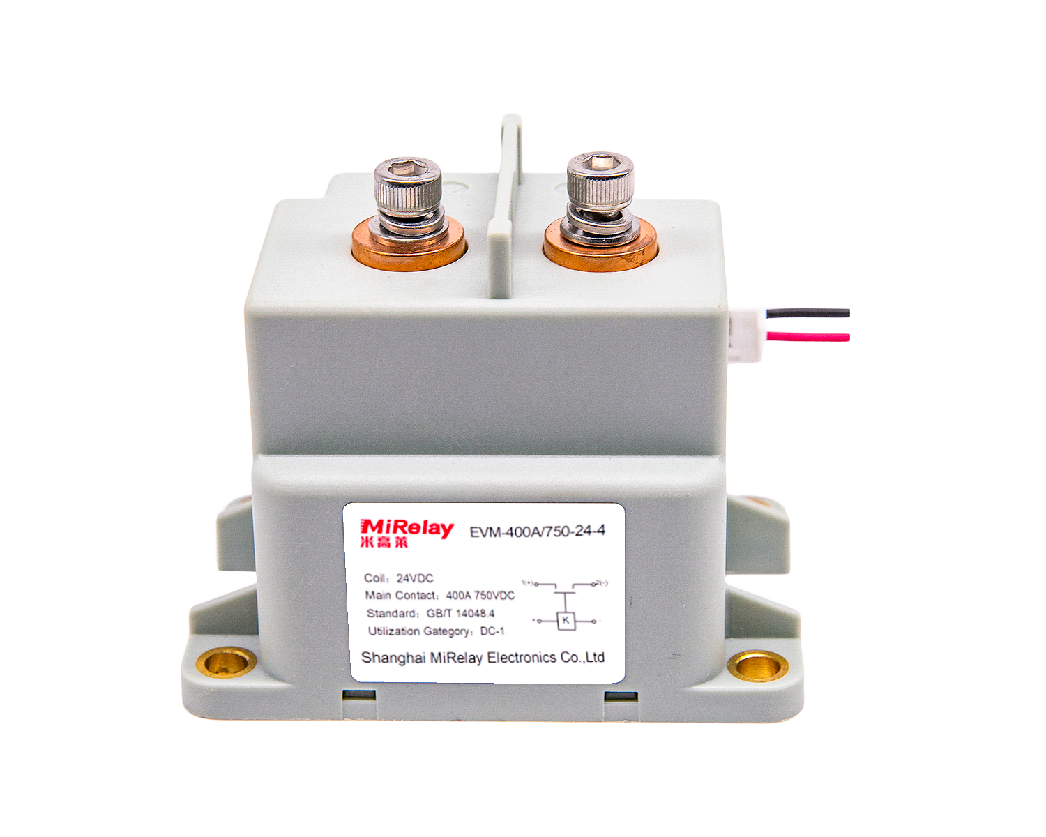
Energy storage systems run on DC, at voltages between 400 V and 1500 V and currents from tens to hundreds of amps. Unlike AC, a DC arc does not cross zero on its own, so interrupting it takes a contactor built for the job. The contactor is also the part that has to work when everything else has failed, which is why selection deserves real attention rather than a line item at the end of the BOM.
What the contactor does in a storage system
- Operation switching: circuit control during system start/stop and charge/discharge cycles
- Emergency protection: rapid disconnection of the high voltage bus during faults
- Maintenance isolation: electrical isolation for service work
Selection parameters
Rated voltage
Common system voltage levels are 400 V DC (small residential and commercial systems), 500 V DC (small to medium), 750 V DC (medium), 1000 V DC (large commercial and industrial), and 1500 V DC (grid-scale). Size the contactor at 1.5–2× system voltage; the margin covers switching transients and keeps the arc chamber inside its comfort zone.
Rated current
Work from the maximum system current, not the nominal. Three numbers matter: continuous operating current, short-time overload (typically 1.5–2× rated for 1–10 seconds), and the inrush during capacitor pre-charge. A contactor sized on continuous current alone will disappoint the first time it has to break a fault.
Arc extinguishing technology
- Ceramic sealed: the right choice for high reliability and 1000 V+ systems
- Gas-sealed: proven for 1000 V+ applications
- Magnetic arc quenching: suitable for 400–750 V systems
Mechanical and electrical life
Storage systems switch often, so life ratings are not optional specs: look for at least 1,000,000 mechanical operations and 100,000 electrical operations at rated load.
Temperature
Industrial enclosures typically call for −40 °C to +85 °C, which our product line covers in full. Remember to derate current at the top of the range; the container interior in summer is hotter than the datasheet’s ambient assumption.
Quick model reference
| System Power | System Voltage | Rated Current | Recommended Model | Package |
|---|---|---|---|---|
| 50 kW | 500 V | 100 A | EVI-100-750 | Epoxy |
| 100 kW | 500 V | 200 A | EVI-200-750 | Epoxy |
| 100 kW | 800 V | 125 A | EVI-150-1000 | Epoxy |
| 200 kW | 800 V | 250 A | EVM-300-1000 | Ceramic |
| 250 kW | 1000 V | 250 A | EVM-300-1500 | Ceramic |
| 400 kW | 1000 V | 400 A | EVM-400-1500 | Ceramic |
Selection mistakes we keep seeing
- Insufficient voltage margin, which shows up as arc extinction failures
- Ignoring temperature derating in hot environments
- Using contact materials that were never meant for DC loads
- Overlooking mechanical life in applications that switch frequently
Getting the contactor right at the design stage costs nothing extra and pays back over the whole system lifecycle in avoided maintenance. For a longer treatment of how these parts behave inside real storage installations, see High Voltage DC Contactors in Energy Storage: A Technical Application Guide, and for voltage-class comparisons, the 400V vs 800V vs 1000V selection guide. Model details are on the EVI series and EVM series pages; for sizing help on a specific project, contact [email protected].