SIP Series
Single In-line Package Reed Relay
1. Product Features
- Molded monolithic frame design
- Optional coil flyback diode protection
- High insulation resistance up to 10¹⁰Ω
- High-speed switching, high reliability
- Long-life sealed contacts
- Optional magnetic shielding to reduce external interference
- Custom design available, RoHS compliant
2. Performance Data
| Parameter | Unit | Value |
|---|---|---|
| Contact Rating | W | 10 - 100 |
| Switching Voltage (Max DC/Peak AC) | V | 100 - 1000 |
| Switching Current (Max DC/Peak AC) | A | 0.25 - 1.0 |
| Carry Current (Max) | A | 0.4 - 2.5 |
| Contact Resistance | mΩ | 150 - 200 |
| Dielectric Strength (Contact to Contact) | VDC | 150 - 4000 |
| Dielectric Strength (Contact to Coil) | VDC | 1400 - 7000 |
| Insulation Resistance | Ω | 10¹⁰ - 10¹² |
| Operate Time | ms | 0.3 - 3.0 |
| Release Time | ms | 0.1 - 3.0 |
| Vibration Resistance (0-2000Hz) | G | 20 |
| Shock Resistance (11ms, 1/2 sine wave) | G | 50 |
| Operating Temperature | °C | -40 ~ +85 |
| Storage Temperature | °C | -40 ~ +105 |
| Expected Life | Ops | 5 × 10⁷ (at 10VDC-10mA) |
3. Coil Parameters
| Rated Voltage (VDC) | Pull-in Voltage (VDC) | Drop-out Voltage (VDC) | Max Voltage (VDC) | Coil Resistance (±10%Ω at 20°C) |
|---|---|---|---|---|
| 5 | 3.75 | 0.6 | 15 | 100 - 500 |
| 12 | 8.6 - 9 | 1 - 1.5 | 18 - 30 | 250 - 1000 |
| 24 | 17.5 - 18 | 2 - 2.5 | 32 - 40 | 1400 - 2000 |
4. Ordering Information
SIP - □□□ - (XXX)
| Position | Description | Options |
|---|---|---|
| ① | Product Model | SIP |
| ② | Contact Form | 1A: Form A (NO), 1B: Form B (NC), 1C: Form C (SPDT) |
| ③ | Coil Voltage | 05: 5VDC, 12: 12VDC, 24: 24VDC |
| ④ | Features | None: Standard, B: With Diode, S: With Magnetic Shield, BS: With Diode & Shield |
| ⑤ | Special Code | Customer special requirement |
5. Product Images
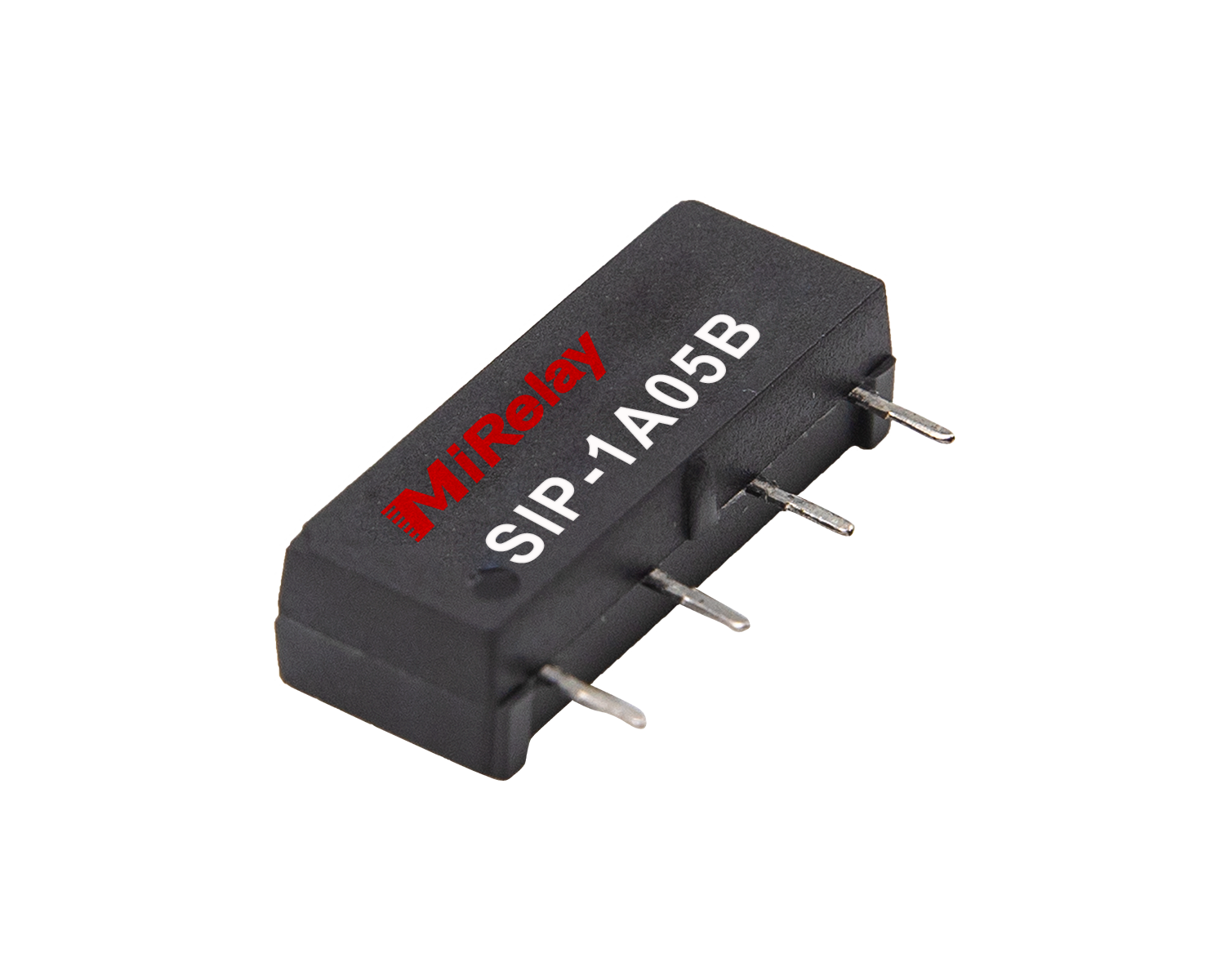
SIP-1A05B

SIP-1A12B
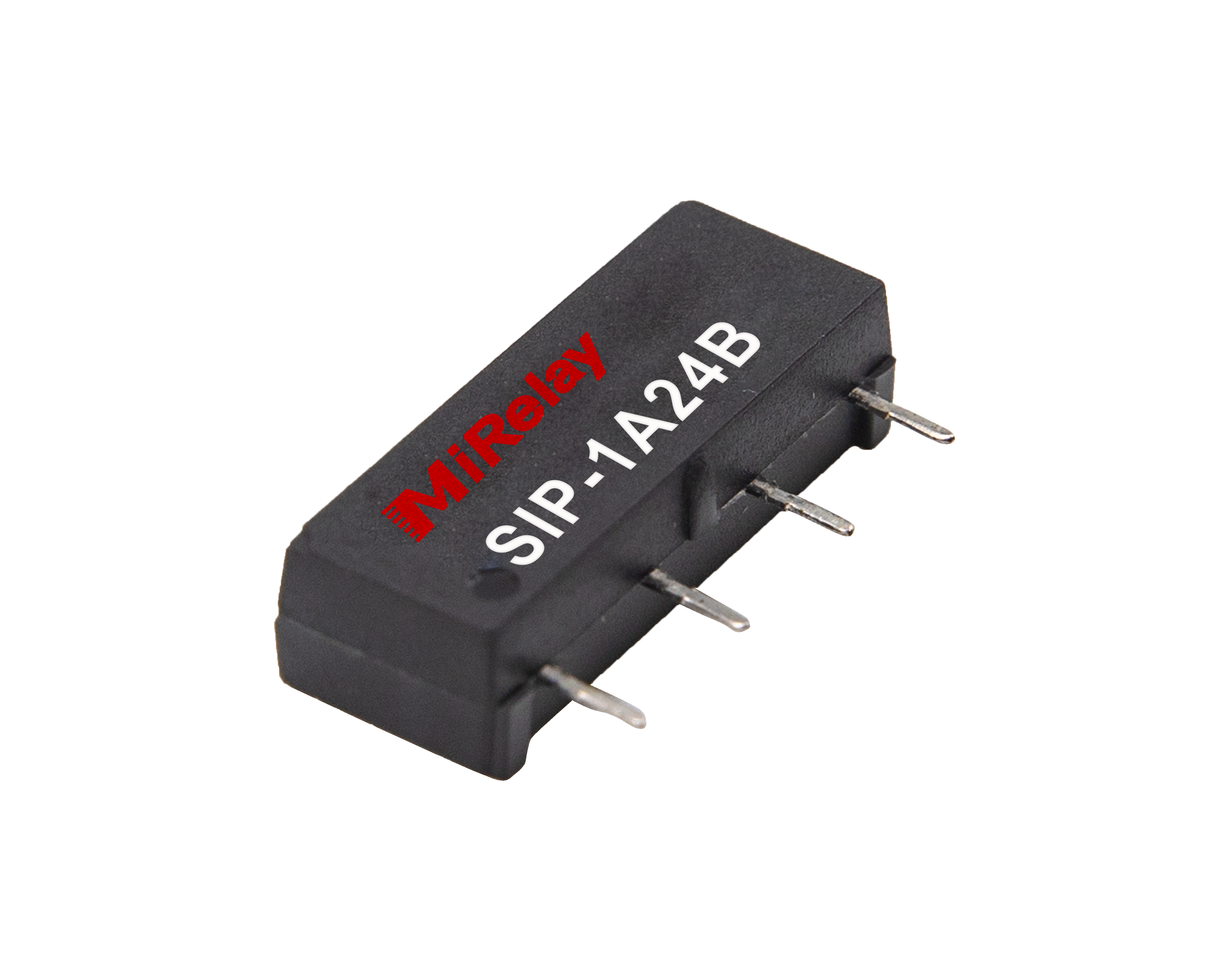
SIP-1A24B
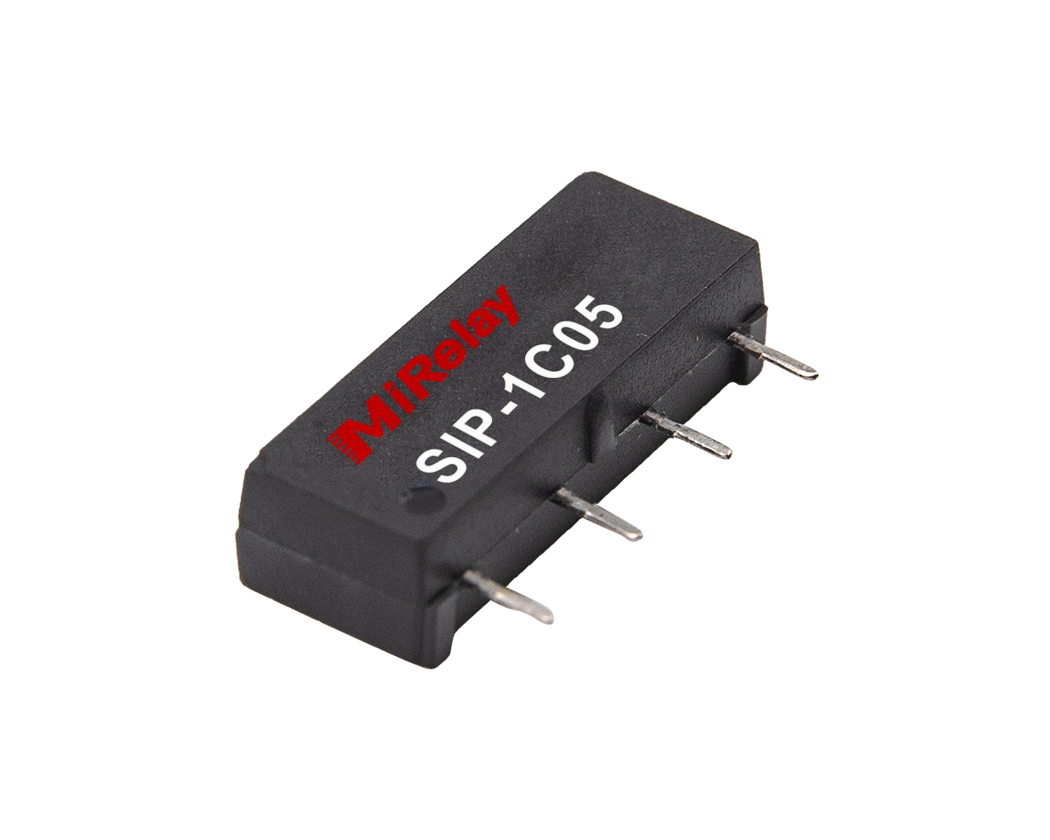
SIP-1C05
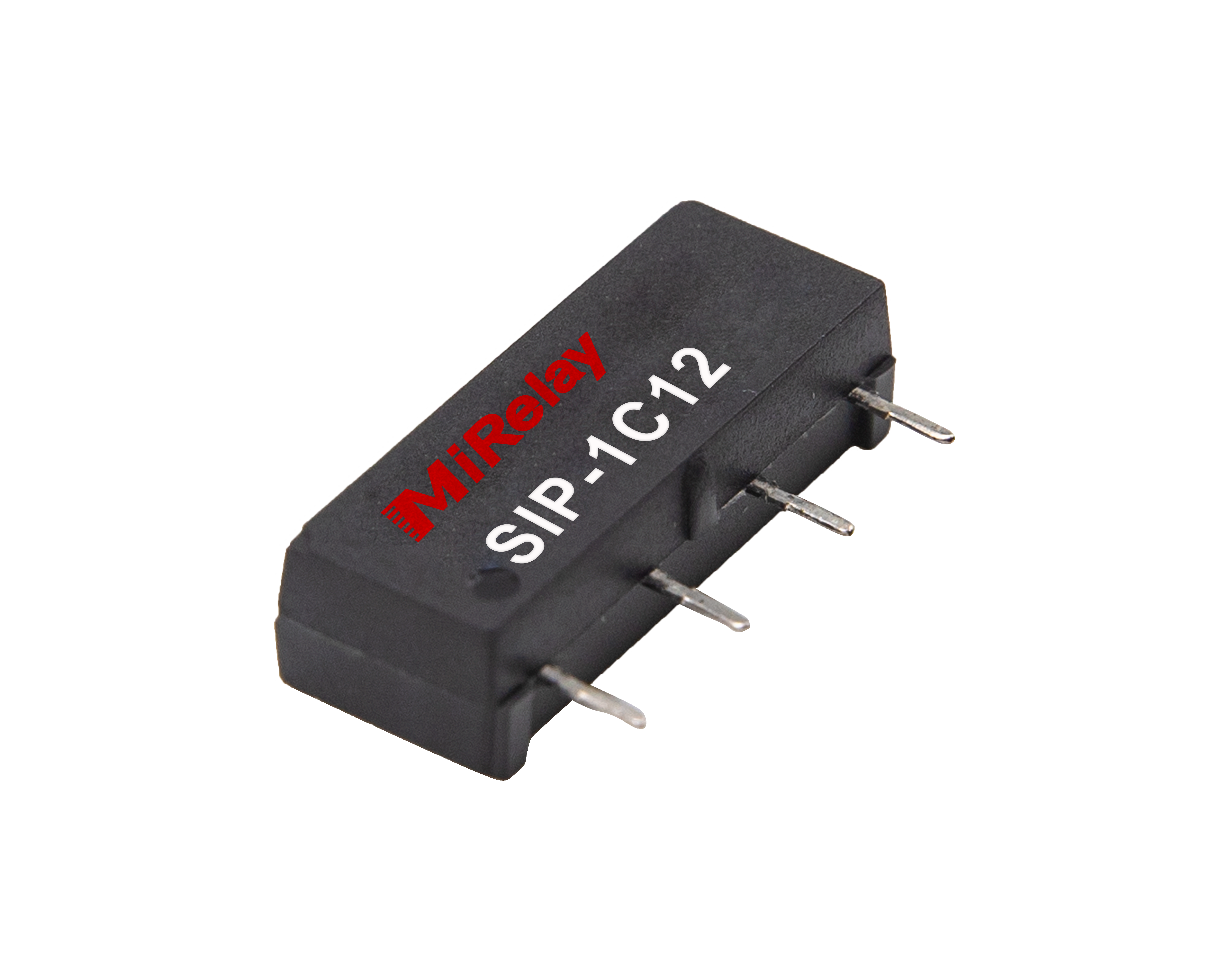
SIP-1C12
6. Outline Drawing
Refer to technical drawings for exact dimensions and mounting configuration. Multiple package options available including standard, shielded, and high-voltage variants.
7. Wiring Diagram
Standard wiring configurations available for all contact forms (1A, 1B, 1C). Optional diode protection and magnetic shielding can be specified.
8. Precautions for Use
- Environment: Avoid installation in areas directly exposed to rain, strong magnetic fields, or near objects with thermal radiation.
- Load Protection: Switching inductive or capacitive loads may produce peak voltage or current. Protection circuits are recommended to prevent relay damage.
- Density: Avoid excessive bulk density in use, which may affect the electrical characteristics of the relay.
- Mechanical Shock: Excessive mechanical shock may cause relay malfunction.
- Soldering: For wave soldering, maximum temperature is 260°C for no more than 5 seconds.