MRS21 Series - Reed Proximity Switch
1. Features
- Output reliable contact switch
- High-end sensor applications
- Withstands temperature up to 130°C
- Suitable for low power operation
- Custom design available
- Conforming to RoHS directive
2. Performance Data
| Parameter | Units | A (NO) - 10W | A (NO) - 70W | A (NO) - 100W | B (NC) / C (SPDT) |
|---|---|---|---|---|---|
| Rated Power (max.) | W | 10 | 70 | 100 | 10 |
| Switching Voltage (Max DC/Peak AC) | V | 180 | AC 300 / DC 350 | 1000 | 175 |
| Switching Current (Max DC/Peak AC) | A | 0.5 | 0.2 | 1.0 | 0.5 |
| Carry Current (max.) | A | 1.25 | 2.0 | 2.5 | 1.0 |
| Contact Resistance (@0.5V & 50mA) | mΩ | 150 | 150 | 150 | 150 |
| Breakdown Voltage | VDC | 250 | 500 | 1500 | 200 |
| Insulation Resistance (Rh <45%, 100V Test) | Ω | 10¹⁰ | 10¹² | 10¹⁰ | 10⁹ |
| Operating Time (max.) | ms | 0.7 | 0.6 | 1.1 | 0.7 |
| Release Time (max.) | ms | 0.05 | 0.05 | 0.05 | 1.5 |
| Capacitance (typ.) | pF | 0.3 | 0.4 | 0.5 | 1.5 |
| Vibration Resistance | G | 20 | 20 | 20 | 20 |
| Shock Resistance (1/2 sine wave, 11ms) | G | 30 | 30 | 30 | 30 |
| Operating Temperature | °C | -40 ~ +130 | -40 ~ +130 | -40 ~ +130 | -40 ~ +130 |
| Storage Temperature | °C | -40 ~ +130 | -40 ~ +130 | -40 ~ +130 | -40 ~ +130 |
3. Example of Order Marking
MRS21 - □ - □ - □ - □ (XXX)
| Position | Description | Options |
| ---------- | ------------- | --------- |
|---|---|---|
| ① | Product model | MRS21 |
| ② | Contact form | 1A: 1 Form A (NO) 1B: 1 Form B (NC) 1C: 1 Form C (SPDT) |
| ③ | Switch characteristic | 1: 10W 2: 70W 3: 100W |
| ④ | Magnetic sensitivity (AT) | A: 05-10; B: 10-15; C: 15-20; D: 20-25; E: 25-30; F: 30-35; G: 35-40 |
| ⑤ | Cable Length (mm) | 1: 200; 2: 300; 3: 500; 4: 1000; 5: 1500; 6: 2000; 7: 3000; 8: 5000 |
| ⑥ | Special code | Customer special requirement |
4. Outline Drawing
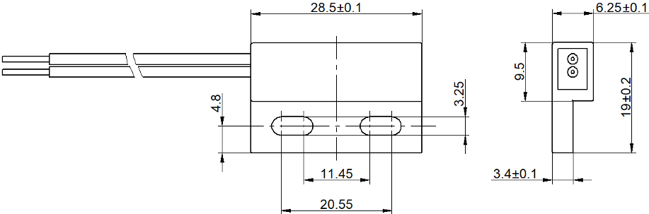
Standard housing dimensions and mounting configuration for MRS21 series reed proximity switches.
5. Layout
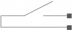
PCB mounting layout and connection diagram for MRS21 series switches.
6. Precautions for Use
1. Environment: Avoid installation in areas directly exposed to rain, strong magnetic fields, or near objects with thermal radiation.
2. Density: Avoid excessive bulk density in use, which may affect the electrical characteristics of the switch.
3. Mechanical Shock: Excessive mechanical shock strength may change its magnetic sensitivity or even damage the switch.
4. Soldering: Use appropriate pin tightening or heat dissipation to prevent mechanical or thermal stress during welding.
5. Wire Handling: The minimum bending distance from the wire to the housing is 5mm, and dragging is prohibited.
Technical Support
For specific parameters and performance details, please refer to the specifications and samples provided by SHR AUTOSENSOR TECH LIMITED.
Performance parameters vary from application area to application area. Customers should choose the appropriate product according to the specific conditions of use.
Contact Information:
SHR AUTOSENSOR TECH LIMITED
📧 Email: [email protected]
🌐 Website: www.reed-relay.com
Disclaimer
This document is for customer reference only. Specifications and parameters may be changed due to product improvement without further notice.
*Document Version: 2.0*
*© 2026 SHR AUTOSENSOR TECH LIMITED. All rights reserved.*