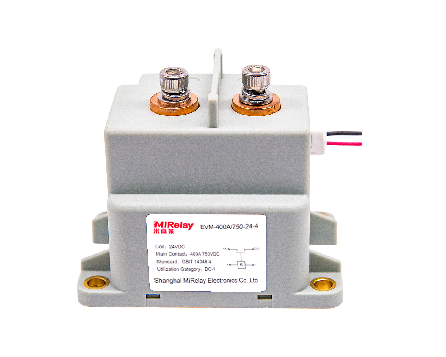
A battery management system does many things, but its most important job is simple: disconnect the pack when something goes wrong. That final disconnect runs through the high voltage DC contactors, which is why BMS engineers spend more selection effort on this one component than on almost anything else in the safety chain. This article covers what the contactor actually does in the pack, how to size it correctly, and where SHR’s EVI and EVM series fit in.
What the contactor does in an EV
A high voltage DC contactor sits between the battery pack and the rest of the vehicle. When everything is normal, it carries the full drive and charging current. When something goes wrong, it has to open reliably, under load, without welding.
In practice the contactor handles four jobs:
- Emergency disconnect: isolate the battery during a crash or fault condition
- Pre-charge: limit inrush current into the inverter’s DC-link capacitors
- Load switching: connect and disconnect high-power loads such as motors and chargers
- Current interruption: break high DC current without destroying the contacts
Because the contactor is the last mechanical element in the protection chain, a single failure here can defeat everything the BMS does upstream: thermal runaway, fire, or a pack that cannot be disconnected in an emergency.
Why a standard relay is not enough
The cost gap between a standard relay and a HV DC contactor tempts some designs toward the cheaper part. The numbers explain why that rarely ends well:
| Parameter | Standard Relay | HV DC Contactor |
|---|---|---|
| DC breaking capacity | 30–50 A typical | 200–400 A+ at 1000 V DC |
| Arc suppression | Limited | Ceramic/epoxy sealed chamber |
| Contact weld resistance | Moderate | High (tungsten alloys) |
| Life expectancy | 100K operations | 1M+ operations |
| Safety certifications | General purpose | IATF 16949, UL, CE |
The failure mode that matters most is welding. A relay that welds shut during a high-current interruption stays closed, exactly when the BMS needs it open. The pack remains connected during the fault the contactor was supposed to interrupt.
Sizing the contactor for the system
Voltage rating: 400V, 800V, or 1000V+
Current EV platforms fall into three voltage classes:
- 400V systems: the current mainstream (Tesla Model 3/Y and most volume EVs)
- 800V systems: the next generation (Porsche Taycan, Hyundai E-GMP, Xiaomi SU7)
- 1000V+ systems: commercial vehicles and energy storage
A practical rule is to rate the contactor at least 20% above the nominal system voltage.
| System Voltage | Recommended Contactor Rating | SHR Series |
|---|---|---|
| 400V nominal | 500–600V DC | EVI-50A (900V) |
| 800V nominal | 1000V DC | EVI-100A/150A |
| 1000V+ | 1200–1500V DC | EVI-200A/250A/300A, EVM series |
Current rating: continuous versus peak
Two different current specs govern selection. Continuous current is what the contactor carries in normal operation; work it out from motor power and efficiency. A 150 kW motor at 400 V draws roughly 375 A continuous before losses, and derating applies at temperature: at 85 °C ambient, figure on losing about 20% of rated capacity.
Peak current covers acceleration and fast charging, and can run 2–3× continuous current for 10–30 seconds. The contactor must carry this without welding, and still interrupt it if a fault occurs mid-pulse.
| Model | Continuous | Peak (30 s) |
|---|---|---|
| EVI-100A | 100 A | 300 A |
| EVI-150A | 150 A | 450 A |
| EVI-200A | 200 A | 600 A |
| EVI-300A | 300 A | 900 A |
Arc suppression: epoxy or ceramic
Breaking high DC current sustains an arc that will destroy contacts, start fires, or leave the circuit connected if the chamber cannot quench it. SHR builds the EVI series with epoxy sealing and the EVM series with ceramic:
- EVI (epoxy sealed): cost-effective, covers most EV applications, −40 °C to +85 °C
- EVM (ceramic sealed): better arc quenching, −40 °C to +125 °C, suited to commercial vehicles and harsh environments
Coil voltage and power
Coils are available in 12 V for auxiliary battery systems, 24 V for commercial vehicles, and 48 V for mild-hybrid systems. Coil power matters more than it first appears. A 10 W difference across two contactors (main plus pre-charge) is a 20 W continuous drain, which is 480 Wh over a day, and that comes out of vehicle range. The EVI/EVM magnetic circuits hold on 5–8 W.
Worked example: 100 kWh pack
Take a representative pack specification:
- 100 kWh battery pack
- 400 V nominal system voltage
- 150 kW peak motor power
- 150 kW DC fast charging
- Operating temperature −30 °C to +60 °C
- Voltage rating: 400 V × 1.2 = 480 V minimum, so select a 900 V+ rated part
- Continuous current: motor 150 kW ÷ 400 V ÷ 0.9 efficiency ≈ 417 A; charging 150 kW ÷ 400 V = 375 A, so select 450 A+ continuous
- Peak current: 417 A × 2.5 ≈ 1040 A
- Temperature derating: about 10% at 60 °C
The recommended configuration for this pack:
- Main contactors: 2× EVI-300A in parallel (600 A continuous, 1800 A peak)
- Pre-charge contactor: EVI-50A with pre-charge resistor
- Ground contactor: EVI-300A for complete isolation
For an 800 V version of the same pack, the layout becomes 2× EVI-200A (1500 V rated, 400 A continuous each) with an EVI-50A (900 V) on pre-charge.
Certifications to check
For automotive BMS applications, ask for documentation on the following before committing to a supplier:
| Certification | Why it matters |
|---|---|
| IATF 16949 | Automotive quality management; consistent manufacturing |
| UL Recognition | Independent safety testing; important for North American markets |
| CE Marking | European compliance; mandatory for EU sales |
| RoHS/REACH | Environmental compliance; required globally |
All EVI and EVM contactors carry these certifications. Request the files during the design phase, not after.
Four mistakes we see often
Sizing down to save cost
A 100 A contactor costs less than a 200 A unit. If it has to interrupt 150 A during an emergency disconnect and fails, the savings will not cover the consequences.
Ignoring temperature derating
A 200 A contactor may only carry 160 A at 85 °C. Ambient temperatures inside the pack enclosure are almost always worse than the datasheet assumes.
One contactor only
Separate positive and negative contactors give full isolation of the pack. Worth the extra part in any safety-critical design.
No pre-charge
Direct connection to the inverter’s capacitors produces a massive inrush. The pre-charge circuit is small, cheap, and prevents contactor damage on every power-up.
What the EVI/EVM series offers
The EVI and EVM lines have served EV and energy storage designs for over ten years, in volumes from prototypes to production packs. The design points that matter most to BMS engineers:
- Compact footprint for tight pack layouts
- Low coil power (5–8 W typical holding)
- Bidirectional current handling for drive and regen
- Wide temperature range: −40 °C to +125 °C (EVM ceramic series)
Manufacturing is IATF 16949 certified, every unit is functionally tested before shipping, and full lot traceability is maintained for quality assurance.
Engineering support
SHR’s engineering team reviews BMS requirements and recommends a configuration, including custom coil voltages, mounting options, and terminal types. Validation testing support, complete datasheets, application notes, and certification files are available on request.
BMS contactor selection comes down to honest numbers: voltage margin, continuous and peak current, temperature derating, and how the arc chamber behaves under fault conditions. The EVI and EVM series cover 450 V to 1500 V and 30 A to 400 A continuous, which spans the architectures currently in production. If your requirements fall outside the standard line, contact the engineering team; custom configurations are routine.
Next steps
- EVI series (epoxy sealed) and EVM series (ceramic sealed) product pages
- High Voltage DC Contactor Selection Guide: 400V vs 800V vs 1000V Systems
- EVI vs EVM comparison guide
- Samples and quotes: [email protected]
- Technical consultation: WhatsApp +86 137 6157 1029
SHR AUTOSENSOR TECH LIMITED designs and manufactures high voltage switching components for EV, energy storage, and industrial applications. Production is IATF 16949 certified.